- 您现在的位置:买卖IC网 > Sheet目录3562 > ISL28433FBZ-T7A (Intersil)IC OPAMP CHOPPR RR .4MHZ 14SOIC
ISL28233, ISL28433
5
FN7692.3
July 26, 2011
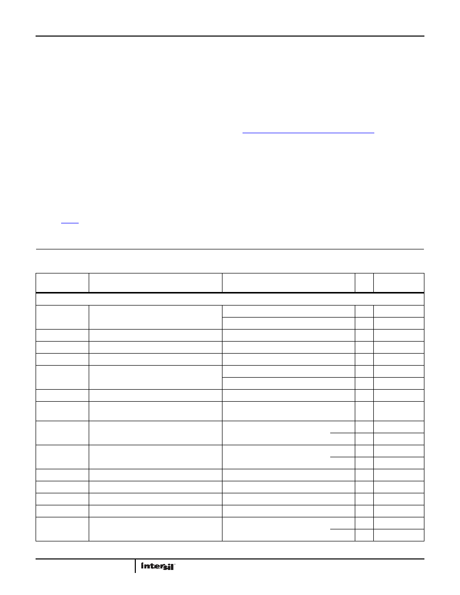
Absolute Maximum Ratings
Thermal Information
Max Supply Voltage V+ to V- . . . . . . . . . . . . . . . . . . . . . . . . . . . . . . . . . . .6.5V
Max Voltage VIN to GND . . . . . . . . . . . . . . . . . . . . (V- - 0.3V) to (V+ + 0.3V)V
Max Input Differential Voltage . . . . . . . . . . . . . . . . . . . . . . . . . . . . . . . . 6.5V
Max Input Current . . . . . . . . . . . . . . . . . . . . . . . . . . . . . . . . . . . . . . . . . 20mA
Max Voltage VOUT to GND (10s) . . . . . . . . . . . . . . . . . . . . . . . . . . . . . . .±3.0V
ESD Tolerance
Human Body Model (Tested per JESD22-A114F) . . . . . . . . . . . . . . 4000V
Machine Model (Tested per JESD22-A115B) . . . . . . . . . . . . . . . . . . 400V
Charged Device Model (Tested per JESD22-C110D) . . . . . . . . . . . 2000V
Latch-Up (Tested per JESD78B) . . . . . . . . . . . . . . . . . . . . . . . . . . . . +125°C
Thermal Resistance (Typical)
θJA (°C/W)
θJC (°C/W)
14 Ld TSSOP (Notes 4, 7) . . . . . . . . . . . . . .
110
40
14 Ld SOIC (Notes 4, 7) . . . . . . . . . . . . . . . .
75
47
14 Ld TDFN (Notes 5, 6) . . . . . . . . . . . . . . .
TBD
8 Ld MSOP (Notes 4, 7) . . . . . . . . . . . . . . . .
180
65
8 Ld SOIC (Notes 4, 7) . . . . . . . . . . . . . . . . .
125
90
8 Ld DFN (Notes 5, 6). . . . . . . . . . . . . . . . . .
53
12
Maximum Storage Temperature Range . . . . . . . . . . . . . .-65°C to +150°C
Pb-Free Reflow Profile . . . . . . . . . . . . . . . . . . . . . . . . . . . . . . . see link below
http://www.intersil.com/pbfree/Pb-FreeReflow.asp
Operating Conditions
Temperature Range . . . . . . . . . . . . . . . . . . . . . . . . . . . . . . .-40°C to +125°C
CAUTION: Do not operate at or near the maximum ratings listed for extended periods of time. Exposure to such conditions may adversely impact product
reliability and result in failures not covered by warranty.
NOTES:
4.
θJA is measured with the component mounted on a high effective thermal conductivity test board in free air. See Tech Brief TB379 for details.
5.
θJA is measured in free air with the component mounted on a high effective thermal conductivity test board with “direct attach” features. See Tech
Brief TB379.
6. For
θJC, the “case temp” location is the center of the exposed metal pad on the package underside.
7. For
θJC, the “case temp” location is taken at the package top center.
Electrical Specifications V+ = 5V, V- = 0V, VCM = 2.5V, TA = +25°C, RL = 10k, unless otherwise specified. Boldface limits apply over
the operating temperature range,-40°C to +125°C.
PARAMETER
DESCRIPTION
CONDITIONS
MIN
(Note 8) TYP
MAX
(Note 8)
UNIT
DC SPECIFICATIONS
VOS
Input Offset Voltage
-6
±2
6
V
T = -40°C to +125°C
-11
-
11
V
TCVOS
Input Offset Voltage Temperature Coefficient
T = -40°C to +125°C
-0.05
0.01
0.05
V/°C
IOS
Input Offset Current
-10
-
pA
TCIOS
Input Offset Current Temperature Coefficient
T = -40°C to +85°C
-
0.11
-
pA/°C
IB
Input Bias Current
T = -40°C to +85°C
-180
-
180
pA
T = -40°C to +125°C
-600
-
600
pA
TCIB
Input Bias Current Temperature Coefficient
T = -40°C to +85°C
-
0.49
-
pA/°C
CMIR
V+ = 5.0V, V- = 0V
Guaranteed by CMRR
-0.1
-
5.1
V
CMRR
Common Mode Rejection Ratio
VCM = -0.1V to 5.1V
118
125
-
dB
115
--
dB
PSRR
Power Supply Rejection Ratio
Vs = 1.8V to 6.0V
110
138
-
dB
110
--
dB
VOH
Output Voltage, High
4.965 4.981
-
V
VOL
Output Voltage, Low
-18
35
mV
AOL
Open Loop Gain
RL = 1MΩ
-174
-
dB
V+
Supply Voltage
Guaranteed by PSRR
1.8
-
6.0
V
IS
Supply Current, Per Amplifier
RL = OPEN
-
18
25
A
--
35
A
发布紧急采购,3分钟左右您将得到回复。
相关PDF资料
ISL28217FBZ-T7A
IC OPAMP GP 1.5MHZ DUAL LP 8SOIC
150204-6002-TH
CONN SOCKET 2MM 4POS T/H 15GOLD
150204-2000-TH
CONN SOCKET 2MM 4POS SMD 15GOLD
P4KE9.1CA-E3/73
TVS 400W 9.1V 5% BIDIR AXIAL
P4KE9.1AHE3/73
TVS 400W 9.1V 5% UNIDIR AXIAL
TSW-123-14-L-D
CONN HEADER 46POS .100" DL GOLD
P4KE9.1A-E3/73
TVS 400W 9.1V 5% UNIDIR AXIAL
P4KE8.2CAHE3/73
TVS 400W 8.2V 5% BIDIR AXIAL
相关代理商/技术参数
ISL28433FRTZ
制造商:INTERSIL 制造商全称:Intersil Corporation 功能描述:Dual and Quad Micropower Chopper Stabilized, RRIO Operational Amplifiers
ISL28433FRTZ-T13
制造商:INTERSIL 制造商全称:Intersil Corporation 功能描述:Dual and Quad Micropower Chopper Stabilized, RRIO Operational Amplifiers
ISL28433FVZ
功能描述:IC OPAMP CHOPPR RR .4MHZ 14TSSOP RoHS:是 类别:集成电路 (IC) >> Linear - Amplifiers - Instrumentation 系列:- 标准包装:1 系列:- 放大器类型:通用 电路数:2 输出类型:满摆幅 转换速率:2.1 V/µs 增益带宽积:3MHz -3db带宽:- 电流 - 输入偏压:1pA 电压 - 输入偏移:2000µV 电流 - 电源:750µA 电流 - 输出 / 通道:16mA 电压 - 电源,单路/双路(±):2.7 V ~ 16 V,±1.35 V ~ 8 V 工作温度:-40°C ~ 125°C 安装类型:表面贴装 封装/外壳:14-SOIC(0.154",3.90mm 宽) 供应商设备封装:14-SOIC 包装:剪切带 (CT) 其它名称:296-10529-1
ISL28433FVZ-T13
功能描述:IC OPAMP CHOPPR RR .4MHZ 14TSSOP RoHS:是 类别:集成电路 (IC) >> Linear - Amplifiers - Instrumentation 系列:- 标准包装:75 系列:MicroAmplifier™ 放大器类型:通用 电路数:1 输出类型:满摆幅 转换速率:0.03 V/µs 增益带宽积:100kHz -3db带宽:- 电流 - 输入偏压:1pA 电压 - 输入偏移:60µV 电流 - 电源:20µA 电流 - 输出 / 通道:5mA 电压 - 电源,单路/双路(±):2.3 V ~ 5.5 V 工作温度:-40°C ~ 85°C 安装类型:表面贴装 封装/外壳:8-SOIC(0.154",3.90mm 宽) 供应商设备封装:8-SOIC 包装:管件
ISL28433FVZ-T7A
功能描述:IC OPAMP CHOPPR RR .4MHZ 14TSSOP RoHS:是 类别:集成电路 (IC) >> Linear - Amplifiers - Instrumentation 系列:- 产品培训模块:Lead (SnPb) Finish for COTS
Obsolescence Mitigation Program 标准包装:1 系列:- 放大器类型:电流检测 电路数:1 输出类型:- 转换速率:- 增益带宽积:125kHz -3db带宽:- 电流 - 输入偏压:- 电压 - 输入偏移:100µV 电流 - 电源:1.1µA 电流 - 输出 / 通道:- 电压 - 电源,单路/双路(±):- 工作温度:-40°C ~ 85°C 安装类型:表面贴装 封装/外壳:4-WFBGA,CSPBGA 供应商设备封装:4-UCSP(2x2) 包装:剪切带 (CT) 其它名称:MAX9634WERS+TCT
ISL28433SOICEVAL1Z
功能描述:EVAL BOARD FOR ISL28433 14SOIC RoHS:是 类别:编程器,开发系统 >> 评估板 - 运算放大器 系列:- 产品培训模块:Lead (SnPb) Finish for COTS
Obsolescence Mitigation Program 标准包装:1 系列:-
ISL28433TSSOPEVAL1Z
功能描述:EVAL BOARD FOR ISL28433 14TSSOP RoHS:是 类别:编程器,开发系统 >> 评估板 - 运算放大器 系列:- 产品培训模块:Lead (SnPb) Finish for COTS
Obsolescence Mitigation Program 标准包装:1 系列:-
ISL28448
制造商:INTERSIL 制造商全称:Intersil Corporation 功能描述:4.5MHz, Single Dual and Quad Precision Rail-to-Rail Input-Output (RRIO) Op Amps with Very Low Input Bias Current